Question 1
Company uses MSTP within their switched LAN. What is the main purpose of Multiple Instance Spanning Tree Protocol (MSTP)?
A. To enhance Spanning Tree troubleshooting on multilayer switches
B. To reduce the total number of spanning tree instances necessary for a particular topology
C. To provide faster convergence when topology changes occur in a switched network
D. To provide protection for STP when a link is unidirectional and BPDUs are being sent but not received
Answer: B
Explanation
Instead of running an STP instance for every VLAN, MSTP runs a number of VLAN-independent STP instances. By allowing a single instance of STP to run for multiple VLANs, MSTP keeps the number of STP instances to minimum (saving switch resources) while optimizing Layer 2 switching environment (load balancing traffic to different paths for different VLANs.).
Question 2
Which of the following specifications will allow you to associate VLAN groups to STP instances so you can provide multiple forwarding paths for data traffic and enable load balancing?
A. IEEE 802.1d (STP)
B. IEEE 802.1s (MST)
C. IEEE 802.1q (CST)
D. IEEE 802.1w (RSTP)
Answer: B
Question 3
Refer to the exhibit. All network links are FastEthernet. Although there is complete connectivity throughout the network, Front Line users have been complaining that they experience slower network performance when accessing the Server Farm than the Reception office experiences. Based on the exhibit, which two statements are true? (Choose two)
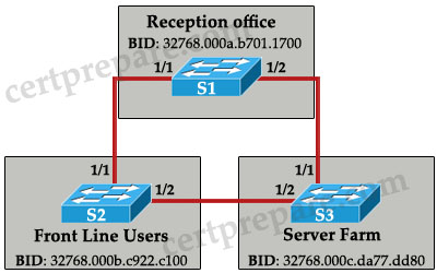 A. Changing the bridge priority of S1 to 4096 would improve network performance.
B. Changing the bridge priority of S1 to 36864 would improve network performance.
C. Changing the bridge priority of S2 to 36864 would improve network performance.
D. Changing the bridge priority of S3 to 4096 would improve network performance.
E. Disabling the Spanning Tree Protocol would improve network performance.
F. Upgrading the link between S2 and S3 to Gigabit Ethernet would improve performance.
Answer: B D
Explanation
All three switches have the same bridge priority (32768 – default value) and S1 has the lowest MAC -> S1 is the root bridge and all traffic must go through it -> Front Line Users (S2) must go through S1 to reach Server Farm (S3). To overcome this problem, S2 or S3 should become the root switch and we can do it by changing the bridge priority of S1 to a higher value (which lower its priority – answer B) or lower the bridge priority value (which higher its priority – answer D)
Question 4
Refer to the exhibit. Initially, LinkA is connected and forwarding traffic. A new LinkB is then attached between SwitchA and HubA. Which two statements are true about the possible result of attaching the second link? (Choose two)
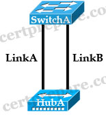 A. The switch port attached to LinkB will not transistion to up.
B. One of the two switch ports attached to the hub will go into blocking mode when a BPDU is received.
C. Both switch ports attached to the hub will transition to the blocking state.
D. A heavy traffic load could cause BPDU transmissions to be blocked and leave a switching loop.
E. The switch port attached to LinkA will immediately transition to the blocking state.
Answer: B D
Explanation
we know that there will have only one Designated port for each segment (notice that the two ports of SwitchA are on the same segment as they are connected to a hub). The other port will be in Blocking state. But how does SwitchA select its Designated and Blocking port? The decision process involves the following parameters inside the BPDU:
* Lowest path cost to the Root
* Lowest Sender Bridge ID (BID)
* Lowest Port ID
In this case, both interfaces of SwitchA have the same “path cost to the root” and “sender bridge ID” so the third parameter “lowest port ID” will be used. Suppose two interfaces of SwitchA are fa0/1 & fa0/2 then SwitchA will select fa0/1 as its Designated port (because fa0/1 is inferior to fa0/2) -> B is correct.
Suppose the port on LinkA (named portA) is in forwarding state and the port on LinkB (named portB) is in blocking state. In blocking state, port B still listens to the BPDUs. If the traffic passing through LinkA is too heavy and the BPDUs can not reach portB, portB will move to listening state (after 20 seconds for STP) then learning state (after 15 seconds) and forwarding state (after 15 seconds). At this time, both portA & portB are in forwarding state so a switching loop will occur -> D is correct.
Question 5
Refer to the exhibit. Switch S1 is running mst IEEE 802.1s. Switch S2 contains the default configuration running IEEE 802.1D. Switch S3 has had the command spanning-tree mode rapid-pvst running IEEE 802.1w. What will be the result?
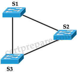 A. IEEE 802.1D and IEEE 802.1w are incompatible. All three switches must use the same standard or no traffic will pass between any of the switches.
B. Switches S1, S2, and S3 will be able to pass traffic between themselves.
C. Switches S1, S2, and S3 will be able to pass traffic between themselves. However, if there is a topology change, Switch S2 will not receive notification of the change.
D. Switches S1 and S3 will be able to exchange traffic but neither will be able to exchange traffic with Switch S2
Answer: B
Explanation
A switch running both MSTP and RSTP supports a built-in protocol migration mechanism that enables it to interoperate with legacy 802.1D switches. If this switch receives a legacy 802.1D configuration BPDU (a BPDU with the protocol version set to 0), it sends only 802.1D BPDUs on that port. An MST switch can also detect that a port is at the boundary of a region when it receives a legacy BPDU, an MST BPDU (version 3) associated with a different region, or an RST BPDU (version 2).
However, the switch does not automatically revert to the MSTP mode if it no longer receives 802.1D BPDUs because it cannot determine whether the legacy switch has been removed from the link unless the legacy switch is the designated switch
Question 6
Refer to the exhibit. Switch S2 contains the default configuration. Switches S1 and S3 both have had the command spanning-tree mode rapid-pvst issued on them. What will be the result?
 A. IEEE 802.1D and IEEE 802.1w are incompatible. All three switches must use the same standard or no traffic will pass between any of the switches.
B. Switches S1, S2. and S3 will be able to pass traffic between themselves.
C. Switches S1, S2. and S3 will be able to pass traffic between themselves. However, if there is a topology change. Switch S2 will not receive notification of the change.
D. Switches S1 and S3 will be able to exchange traffic but neither will be able to exchange traffic with Switch S2.
Answer: B
Question 7
Which two statements are true when the extended system ID feature is enabled? (Choose two)
A. The BID is made up of the bridge priority value (2 bytes) and bridge MAC address (6 bytes).
B. The BID is made up of the bridge priority (4 bits), the system ID (12 bits), and a bridge MAC address (48 bits).
C. The BID is made up of the system ID (6 bytes) and bridge priority value (2 bytes).
D. The system ID value is the VLAN ID (VID).
E. The system ID value is a unique MAC address allocated from a pool of MAC addresses assigned to the switch or module.
F. The system ID value is a hex number used to measure the preference of a bridge in the spanning-tree algorithm.
Answer: B D
Explanation
In short, with the use of IEEE 802.1t spanning-tree extensions, some of the bits previously used for the switch priority are now used for the extended system ID
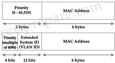 Only four high-order bits of the 16-bit Bridge Priority field carry actual priority. Therefore, priority can be incremented only in steps of 4096. In most cases, the Extended System ID holds the VLAN ID. For example, if our VLAN ID is 5 and we use the default bridge priority 32768 then the 16-bit Priority will be 32768 + 5 = 32773.
Note: The MAC address is reserved when the extended system ID feature is enabled.
Question 8
Which set of statements about Spanning Tree Protocol default timers is true?
A.
The hello time is 2 seconds.
The forward delay is 10 seconds.
The max_age timer is 15 seconds.
B.
The hello time is 2 seconds.
The forward delay is 15 seconds.
The max_age timer is 20 seconds.
C.
The hello time is 2 seconds.
The forward delay is 20 seconds.
The max_age timer is 30 seconds.
D.
The hello time is 5 seconds.
The forward delay is 10 seconds.
The max_age timer is 15 seconds.
E.
The hello time is 5 seconds.
The forward delay is 15 seconds.
The max_age timer is 20 seconds.
Answer: B
Explanation
There are several STP timers, as this list shows:
* Hello - The hello time is the time between each bridge protocol data unit (BPDU) that is sent on a port. This time is equal to 2 seconds (sec) by default, but you can tune the time to be between 1 and 10 sec.
* Forward delay – The forward delay is the time that is spent in the listening and learning state. This time is equal to 15 sec by default, but you can tune the time to be between 4 and 30 sec.
* Max age – The max age timer controls the maximum length of time that passes before a bridge port saves its configuration BPDU information. This time is 20 sec by default, but you can tune the time to be between 6 and 40 sec.
Question 9
Refer to the exhibit. Switch 15 is configured as the root switch for VLAN 10 but not for VLAN 20. If the STP configuration is correct, what will be true about Switch 15?
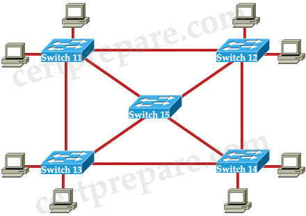 A. All ports will be in forwarding mode.
B. All ports in VLAN 10 will be in forwarding mode.
C. All ports in VLAN 10 will be in forwarding mode and all ports in VLAN 20 will be in blocking mode.
D. All ports in VLAN 10 will be in forwarding mode and all ports in VLAN 20 will be in standby mode.
Answer: B
Explanation
All ports on root bridge are designated ports, which are in forwarding state but notice in this case Switch 15 is the root switch for VLAN 10 -> all ports in VLAN 10 will be in forwarding state. We can not say anything about the modes of ports of Switch 15 in other VLANs.
Question 10
Refer to the exhibit. STP has been implemented in the network. Switch SW_A is the root switch for the default VLAN. To reduce the broadcast domain, the network administrator decides to split users on the network into VLAN 2 and VLAN 10. The administrator issues the command spanning-tree vlan 2 root primary on switch SW_A. What will happen as a result of this change?
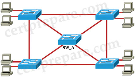 A. All ports of the root switch SW_A will remain in forwarding mode throughout the reconvergence of the spanning tree domain.
B. Switch SW_A will change its spanning tree priority to become root for VLAN 2 only.
C. Switch SW_A will remain root for the default VLAN and will become root for VLAN 2.
D. No other switch in the network will be able to become root as long as switch SW_A is up and running.
Answer: C
Explanation
This command sets the switch to become root for a given VLAN. It works by lowering the priority of the switch until it becomes root. Once the switch is root, it will not prevent any other switch from becoming root. In particular, if the current root bridge is greater than 24576 then our switch will drop to 24576. If the current root bridge is less than 24576, our new bridge priority will be (Priority value of the current root bridge – 4096).
This command does not affect other VLAN so SW_A will remain root for the default VLAN -> C is correct.
Note: This command is not shown in a Catalyst switch configuration because the command is actually a macro executing other switch commands.
Question 11
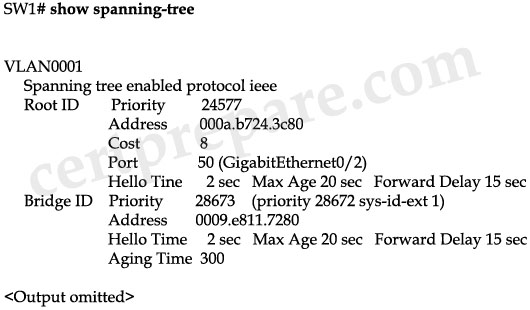
Refer to the exhibit. Based on the output of the show spanning-tree command, which statement is true?
A. Switch SW1 has been configured with the spanning-tree vlan 1 root primary global configuration command.
B. Switch SW1 has been configured with the spanning-tree vlan 1 root secondary global configuration command.
C. Switch SW1 has been configured with the spanning-tree vlan 1 priority 24577 global configuration command.
D. Switch SW1 has been configured with the spanning-tree vlan 1 hello-time 2 global configuration command.
E. The root bridge has been configured with the spanning-tree vlan 1 root secondary global configuration command.
Answer: B
Explanation
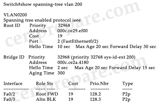
The command “spanning-tree vlan 1 root secondary” sets its bridge ID to a value which is higher than the current root bridge but lower than other switches in the network -> If the current root bridge fails, Sw1 will become the root bridge.
If no priority has been configured, every switch will have the same default priority of 32768. Assuming all other switches are at default priority, the spanning-tree vlan vlan-id root primary command sets a value of 24576. Also, assuming all other switches are at default priority, the spanning-tree vlan vlan-id root secondary command sets a value of 28672.
In this question, the bridge priority of Sw1 is 28673, not 28672 because the extended system ID (indicated as sys-id-ext) is 1, indicating this is the STP instance for VLAN 1. In fact, the bridge priority is 28672.
Question 12
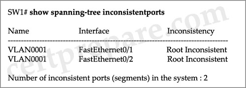
Refer to the exhibit. On the basis of the output of the show spanning-tree inconsistentports command, which statement about interfaces FastEthernet 0/1 and FastEthernet 0/2 is true?
A. They have been configured with the spanning-tree bpdufilter disable command.
B. They have been configured with the spanning-tree bpdufilter enable command.
C. They have been configured with the spanning-tree bpduguard disable command.
D. They have been configured with the spanning-tree bpduguard enable command.
E. They have been configured with the spanning-tree guard loop command.
F. They have been configured with the spanning-tree guard root command.
Answer: F
Explanation
We can configure the root guard feature to prevent unauthorized switches from becoming the root bridge. When you enable root guard on a port, if that port receives a superior BPDU, instead of believing the BPDU, the port goes into a root-inconsistent state. While a port is in the root-inconsistent state, no user data is sent across it. However, after the superior BPDUs stop, the port returns to the forwarding state.
 For example, in the topology above suppose S1 is the current root bridge. If a hacker plugs a switch on S3 which sends superior BPDUs then it will become the new root bridge, this will also change the traffic path and may result in a traffic jam. By enabling root guard on S3 port, if spanning-tree calculations cause an interface to be selected as the root port, the interface transitions to the root-inconsistent (blocked) state instead to prevent the hacker’s switch from becoming the root switch or being in the path to the root.
Question 13
Refer to the exhibit. What information can be derived from the output?
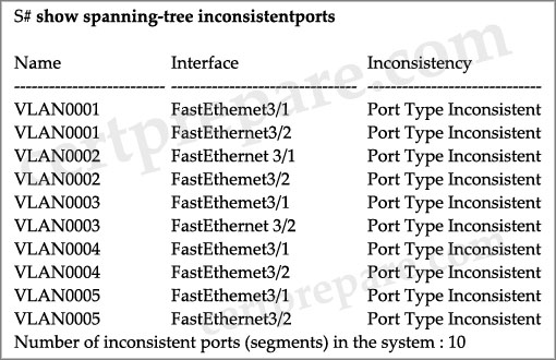
A. Devices connected to interfaces FastEthemet3/1 and FastEthemet3/2 are sending BPDUs with a superior root bridge parameter and no traffic is forwarded across the ports. Once inaccurate BPDUs have been stopped, the interfaces will need to be administratively shut down, and brought back up, to resume normal operation.
B. Devices connected to interfaces FastEthemet3/1 and FastEthernet3/2 are sending BPDUs with a superior root bridge parameter, but traffic is still forwarded across the ports.
C. Devices connected to interfaces FastEthemet3/1 and FastEthemet3/2 are sending BPDUs with a superior root bridge parameter and no traffic is forwarded across the ports. Once inaccurate BPDUs have been stopped, the interfaces automatically recover and resume normal operation.
D. Interfaces FastEthemet3/1 and FastEthemet3/2 are candidate for becoming the STP root port, but neither can realize that role until BPDUs with a superior root bridge parameter are no longer received on at least one of the interfaces.
Answer: C
Question 14
Which statement is correct about RSTP port roles?
A. The designated port is the switch port on every nonroot bridge that is the chosen path to the root bridge. There can be only one designated port on every switch. The designated port assumes the forwarding state in a stable active topology. All switches connected to a given segment listen to all BPDUs and determine the switch that will be the root switch for a particular segment.
B. The disabled port is an additional switch port on the designated switch with a redundant link to the segment for which the switch is designated. A disabled port has a higher port 10 than the disabled port on the designated switch. The disabled port assumes the discarding state in a stable active topology.
C. The backup port is a switch port that offers an alternate path toward the root bridge. The backup port assumes a discarding state in a stable, active topology. The backup port will be present on nondesignated switches and will make a transition to a designated port if the current designated path fails.
D. The root port is the switch port on every nonroot bridge that is the chosen path to the root bridge. There can be only one root port on every switch. The root port assumes the forwarding state in a stable active topology.
Answer: D
Question 15
How are STP timers and state transitions affected when a topology change occurs in an STP environment?
A. All ports will temporarily transition to the learning state for a period equal to the max age timer plus the forward delay interval.
B. All ports will transition temporarily to the learning state for a period equal to the forward delay interval.
C. The default aging time for MAC address entries will be reduced for a period of the max age timer plus the forward delay interval.
D. The default hello time for configuration BPDUs will be reduced for the period of the max age timer.
Answer: C
Explanation
If a switch stops receiving Hellos, it means that there is a failure in the network. The switch will initiate the process of changing the Spanning-tree topology. The process requires the use of 3 STP timers:
* Hello - the time between each bridge protocol data unit (BPDU) that is sent on a port. This time is equal to 2 seconds (sec) by default, but you can tune the time to be between 1 and 10 sec.
* Forward delay – the time that is spent in the listening and learning state. This time is equal to 15 sec by default, but you can tune the time to be between 4 and 30 sec.
* Max age – maximum length of time a BPDU can be stored without receiving an update.. This time is 20 sec by default, but you can tune the time to be between 6 and 40 sec.
Max Age is the time that a bridge stores a BPDU before discarding it.
Switches (Bridges) keep its MAC address table entries for 300 seconds (5 minutes, known as aging time), by default. When a network topology change happens, the Switch (Bridge) temporarily lowers the aging time to the same as the forward delay time (15 seconds) to relearn the MAC address changes happened because of topology change.
This is important because normally only after five minutes an entry is aged out from the MAC address table of the switch and the network devices could be unreachable for up to 5 minutes. This is known as a black hole because frames can be forwarded to a device, which is no longer available.
Notice that shortening the aging time to 15 seconds does not flush the entire table, it just accelerates the aging process. Devices that continue to “speak” during the 15-second age-out period never leave the bridging table.
Therefore in this question, to be clearer answer C should state “The default aging time for MAC address entries will be reduced to forward_delay time for a period of the max age timer plus the forward delay interval.”
Question 16
Refer to the exhibit. The command spanning-tree guard root is configured on interface Gi0/0 on both switch S2 and S5. The global configuration command spanning-tree uplinkfast has been configured on both switch S2 and S5. The link between switch S4 and S5 fails. Will Host A be able to reach Host B?
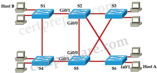 A. Fifty percent of the traffic will successfully reach Host B, and fifty percent will dead-end at switch S3 because of a partial spanning-tree loop.
B. No. Traffic will pass from switch S6 to S2 and dead-end at S2.
C. No. Traffic will loop back and forth between switch S6 and Host A.
D. No. Traffic will loop back and forth between switches S2 and S3.
E. Yes. Traffic will pass from switch S6 to S2 to S1.
Answer: E
Explanation
First we should understand about UpLinkFast.
 Suppose S1 is the root bridge in the topology above. S3 is connected to S1 via two paths: one direct path and another goes through S2. Suppose the port directly connected to S1 is root port -> port connected to S2 will be in Blocking state. If the primary link goes down, the blocked port will need about 50 seconds to move from Blocking -> Listening -> Learning -> Forwarding to be used.
To shorten the downtime, a feature called Uplink Fast can be used. When the primary (root) link fails, another blocked link can be brought up immediately for use. When UplinkFast is enabled, it is enabled for the entire switch and all VLANs. It cannot be enabled for individual VLANs.
In this question, the Root Guard feature has been enabled on Gi0/0 of S2 & S5 so these two Gi0/0 ports cannot be root ports and cannot forward traffic -> the link between S2 & S6 must be used.
Note: The idea of Uplink Fast is based on blocked ports which are possible to become a root port. Therefore the Uplink Fast feature is not allowed on the root bridge -> S2 & S5 cannot be root bridges in this case.
Question 17
Refer to the exhibit. The command spanning-tree guard root is configured on interface Gi0/0 on both switch S2 and S5. The global configuration command spanning-tree uplinkfast has been configured on both switch S2 and S5. The link between switch S4 and S5 fails. Will Host A be able to reach Host B?
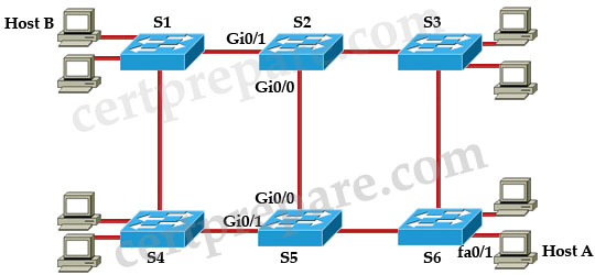
A. Yes. Traffic can pass either from switch S6 to S3 to S2 to S1, or, from switch S6 to S5 to S2 to S1.
B. No. Traffic will pass from switch S6 to S5 and dead-end at interface Gi0/0.
C. No. Traffic will loop back and forth between switch S5 and S2.
D. Yes. Traffic will pass from switch S6 to S3 to S2 to S1.
E. No. Traffic will either pass from switch S6 to S5 and dead-end, or traffic will pass from switch S6 to S3 to S2 and dead-end.
Answer: D
Explanation
Same explanation as Question 6. When the link between S4 – S5 goes down, Gi0/0 on S5 cannot become root port because of Root Guard feature on it. But maybe Host A can’t reach host B in the first 15 seconds after the link between S4 & S5 fails by default. It is the time for S5 to clear the MAC address table.
Question 18
Which two statements about the various implementations of STP are true? (Choose two)
A. Common Spanning Tree maintains a separate spanning-tree instance for each VLAN configured in the network.
B. The Spanning Tree Protocol (STP) is an evolution of the IEEE 802.1w standard.
C. Per-VLAN Spanning Tree (PVST) supports 802.1Q trunking.
D. Per-VLAN Spanning Tree Plus (PVST+) is an enhancement to 802.1Q specification and is supported only on Cisco devices.
E. Rapid Spanning Tree Protocol (RSTP) includes features equivalent to Cisco PortFast, UplinkFast, and BackboneFast for faster network reconvergence.
F. Multiple Spanning Tree (MST) assumes one spanning-tree instance for the entire Layer 2 network, regardless of the multiple number of VLANs.
Answer: D E
Explanation
Common Spanning Tree only uses one spanning-tree instance for all VLANs in the network -> A is not correct.
Rapid Spanning Tree Protocol (RSTP; IEEE 802.1w) can be seen as an evolution of the 802.1D standard more than a revolution. The 802.1D terminology remains primarily the same. Most parameters have been left unchanged so users familiar with 802.1D can rapidly configure the new protocol comfortably -> B is not correct.
Per-VLAN spanning tree protocol plus (PVST+) is a Cisco proprietary protocol that expands on the Spanning Tree Protocol (STP) by allowing a separate spanning tree for each VLAN. Cisco first developed this protocol as PVST, which worked with the Cisco ISL trunking protocol, and then later developed PVST+ which utilizes the 802.1Q trunking protocol. PVST+ allows interoperability between CST and PVST in Cisco switches -> C is not correct but D is correct.
RSTP significantly reduces the time to reconverge the active topology of the network when changes to the physical topology or its configuration parameters occur. RSTP supports Edge Ports (similar to PortFast), UplinkFast, and BackboneFast for faster network reconvergence. Rapid Spanning Tree Protocol (RSTP) can also revert back to 802.1D STP for interoperability with older switches and existing infrastructures -> E is correct.
Multiple Spanning Tree can map one or more VLANs to a single STP instance. Multiple instances of STP can be used (hence the name MST), with each instance supporting a different group of VLANs. For example, instead of creating 50 STP separate STP instances for 50 VLANs, we can create only 2 STP instances – each for 25 VLANs. This helps saving switch resources -> F is not correct.
Question 19
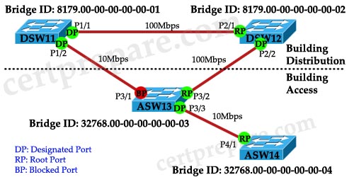
Given the diagram and assuming that STP is enabled on all switch devices, which two statements are true? (Choose two)
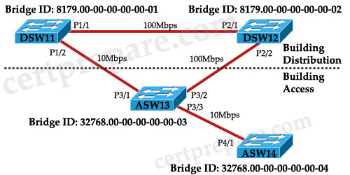 A. DSW11 will be elected the root bridge.
B. DSW12 will be elected the root bridge.
C. ASW13 will be elected the root bridge.
D. P3/1 will be elected the nondesignated port.
E. P2/2 will be elected the nondesignated port.
F. P3/2 will be elected the nondesignated port.
Answer: A D
Explanation
If all the switches are turned on at the same time, DSW11 will win the election and become Root Bridge because it has lowest Bridge ID (including Bridge Priority and MAC address) so all of its ports are Designated Port (forwarding state).
Also P2/1, P3/2 and P4/1 become Root Ports because they are closest to the Root Bridge (in terms of path cost) for each switch.
P3/1 will be Nondesignated (Blocked) Port because P1/2 must be a Designated Port (of course P1/2 advertises better BPDU, in other words better Bridge ID, than P3/1).
Question 20
Which two RSTP port roles include the port as part of the active topology? (Choose two)
A. root
B. designated
C. alternate
D. backup
E. forwarding
F. learning
Answer: A B
Question 21
What is the result of entering the command spanning-tree loopguard default?
A. The command enables both loop guard and root guard.
B. The command changes the status of loop guard from the default of disabled to enabled.
C. The command activates loop guard on point-to-multipoint links in the switched network.
D. The command will disable EtherChannel guard.
Answer: B
Explanation
This command is used in global configuration mode to enable loop guard on all ports of a given switch. To disable it, use the “no” keyword at the beginning of this command.
Question 22
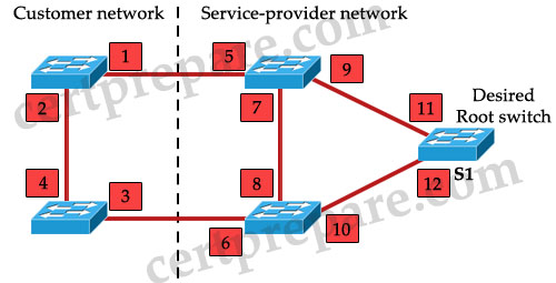
Refer to the exhibit. The service provider wants to ensure that switch S1 is the root switch for its own network and the network of the customer. On which interfaces should root guard be configured to ensure that this happens?
 A. interfaces 1 and 2
B. interfaces 1,2,3, and 4
C. interfaces 1, 3, 5, and 6
D. interfaces 5 and 6
E. interfaces 5, 6, 7, and 8
F. interfaces 11 and 12
Answer: D
Explanation
Let’s see what will happen if we set port 5 & 6 as “root guard” ports:
First, notice that the “root guard” command cannot be used on root switch (because this command is based on blocked port – while a root switch can’t have a blocked port -> two middle switches cannot become root bridges.
Moreover, the neighbor switch which has its port connected with this “root guard” port can’t be the root bridge. For example if we configure port 6 as “root guard” port, the left-bottom switch (the switch with ports 3, 4) can’t be root bridge because that will make port 6 root port. Therefore by configuring port 5 & 6 as “root guard” ports, two switches in the “Customer network” cannot become root bridge.
Question 23
Examine the diagram. A network administrator has recently installed the above switched network using 3550s and would like to control the selection of the root bridge. Which switch should the administrator configure as the root bridge and which configuration command must the administrator enter to accomplish this?
 A. DSW11(config)# spanning-tree vlan 1 priority 4096
B. DSW12(config)# set spanning-tree priority 4096
C. ASW13(config)# spanning-tree vlan 1 priority 4096
D. DSW11(config)# set spanning-tree priority 4096
E. DSW12(config)# spanning-tree vlan 1 priority 4096
F. ASW13(config)# set spanning-tree priority 4096
Answer: E
Explanation
First, only switches in Distribution section should become root bridge -> only DSW11 or DSW12 should be chosen.
The traffic passing root bridge is always higher than other switches so we should choose switch with highest speed connection to be root bridge -> DSW12 with two 100Mbps connections should be chosen.
Also, the correct command to change priority value for a specific VLAN is spanning-treee vlan VLAN-ID priority Priority-number.
Question 24
What must be the same to make multiple switches part of the same Multiple Spanning Tree (MST)?
A. VLAN instance mapping and revision number
B. VLAN instance mapping and member list
C. VLAN instance mapping, revision number, and member list
D. VLAN instance mapping, revision number, member list, and timers
Answer: A
Explanation
MST maps multiple VLANs that have the same traffic flow requirements into the same spanning-tree instance. The main enhancement introduced by MST raises the problem, however, of determining what VLAN is to be associated with what instance. More precisely, based on received BPDUs, devices need to identify these instances and the VLANs that are mapped to the instance.
To be part of a common MST region, a group of switches must share the same configuration attributes. In particular, the configuration name (or region name – 32 bits), revision number (16 bits), and VLAN mapping (associate VLANs with spanning-tree instances) need to be the same for all the switches within the same region.
An example of configuring MST on a switch is shown below:
Question 25
Which three items are configured in MST configuration submode? (Choose three)
A. Region name
B. Configuration revision number
C. VLAN instance map
D. IST STP BPDU hello timer
E. CST instance map
F. PVST+ instance map
Answer: A B C
Question 26
Which three statements about the MST protocol (IEEE 802.1S) are true? (Choose three)
A. To verify the MST configuration, the show pending command can be used in MST configuration mode.
B. When RSTP and MSTP are configured; UplinkFast and BackboneFast must also be enabled.
C. All switches in the same MST region must have the same VLAN-to-instance mapping, but different configuration revision numbers.
D. All switches in an MST region, except distribution layer switches, should have their priority lowered from the default value 32768.
E. An MST region is a group of MST switches that appear as a single virtual bridge to adjacent CST and MST regions.
F. Enabling MST with the “spanning-tree mode mst” global configuration command also enables RSTP.
Answer: A E F
Explanation
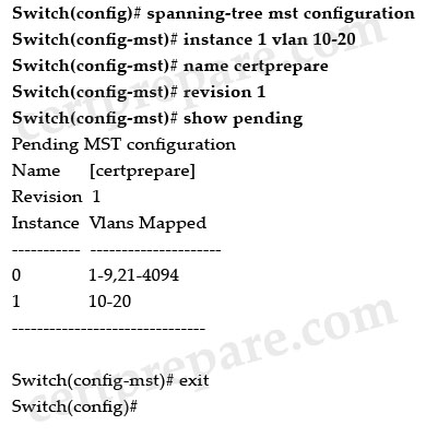
The show pending command can be used to verify the MST configuration (pending configuration). An example of this command is shown below:
Note:
The above commands do these tasks:
+ Enter MST configuration mode
+ Map VLANs 10 to 20 to MST instance 1
+ Name the region certprepare
+ Set the configuration revision to 1
+ Display the pending configuration
+ Apply the changes, and return to global configuration mode
The MST region appears as a single bridge to spanning tree configurations outside the region -> a MST region appears as a single virtual bridge to adjacent CST and MST regions -> E is correct.
By enabling MST you also enable RSTP because MST relies on the RSTP configuration to operate -> F is correct.
Question 27
Which two statements concerning STP state changes are true? (Choose two)
A. Upon bootup, a port transitions from blocking to forwarding because it assumes itself as root.
B. Upon bootup, a port transitions from blocking to listening because it assumes itself as root.
C. Upon bootup, a port transitions from listening to forwarding because it assumes itself as root.
D. If a forwarding port receives no BPDUs by the max_age time limit, it will transition to listening.
E. If a forwarding port receives an inferior BPDU, it will transition to listening.
F. If a blocked port receives no BPDUs by the max_age time limit, it will transition to listening.
Answer: B F
Question 28
Which statement correctly describes the Cisco implementation of RSTP?
A. PortFast, UplinkFast, and BackboneFast specific configurations are ignored in Rapid PVST mode.
B. RSTP is enabled globally and uses existing STP configuration.
C. Root and alternative ports transition immediately to the forwarding state.
D. Convergence is improved by using sub-second timers for the blocking, listening, learning, and forwarding port states.
Answer: B
Explanation
To turn on RSTP, use this command in global configuration mode:
Note: This command turn on both MST & RSTP.
Question 29
The network administrator maps VLAN 10 through 20 to MST instance 2. How will this information be propagated to all appropriate switches?
A. Information will be carried in the RSTP BPDUs.
B. It will be propagated in VTP updates.
C. Information stored in the Forwarding Information Base and the switch will reply on query.
D. Multiple Spanning Tree must be manually configured on the appropriate switches.
Answer: D
Question 30
Which MST configuration statement is correct?
A. MST configurations can be propagated to other switches using VTP.
B. After MST is configured on a Switch, PVST+ operations will also be enabled by default.
C. MST configurations must be manually configured on each switch within the MST region.
D. MST configurations only need to be manually configured on the Root Bridge.
E. MST configurations are entered using the VLAN Database mode on Cisco Catalyst switches.
Answer: C
Company uses MSTP within their switched LAN. What is the main purpose of Multiple Instance Spanning Tree Protocol (MSTP)?
A. To enhance Spanning Tree troubleshooting on multilayer switches
B. To reduce the total number of spanning tree instances necessary for a particular topology
C. To provide faster convergence when topology changes occur in a switched network
D. To provide protection for STP when a link is unidirectional and BPDUs are being sent but not received
Answer: B
Explanation
Instead of running an STP instance for every VLAN, MSTP runs a number of VLAN-independent STP instances. By allowing a single instance of STP to run for multiple VLANs, MSTP keeps the number of STP instances to minimum (saving switch resources) while optimizing Layer 2 switching environment (load balancing traffic to different paths for different VLANs.).
Question 2
Which of the following specifications will allow you to associate VLAN groups to STP instances so you can provide multiple forwarding paths for data traffic and enable load balancing?
A. IEEE 802.1d (STP)
B. IEEE 802.1s (MST)
C. IEEE 802.1q (CST)
D. IEEE 802.1w (RSTP)
Answer: B
Question 3
Refer to the exhibit. All network links are FastEthernet. Although there is complete connectivity throughout the network, Front Line users have been complaining that they experience slower network performance when accessing the Server Farm than the Reception office experiences. Based on the exhibit, which two statements are true? (Choose two)

B. Changing the bridge priority of S1 to 36864 would improve network performance.
C. Changing the bridge priority of S2 to 36864 would improve network performance.
D. Changing the bridge priority of S3 to 4096 would improve network performance.
E. Disabling the Spanning Tree Protocol would improve network performance.
F. Upgrading the link between S2 and S3 to Gigabit Ethernet would improve performance.
Answer: B D
Explanation
All three switches have the same bridge priority (32768 – default value) and S1 has the lowest MAC -> S1 is the root bridge and all traffic must go through it -> Front Line Users (S2) must go through S1 to reach Server Farm (S3). To overcome this problem, S2 or S3 should become the root switch and we can do it by changing the bridge priority of S1 to a higher value (which lower its priority – answer B) or lower the bridge priority value (which higher its priority – answer D)
Question 4
Refer to the exhibit. Initially, LinkA is connected and forwarding traffic. A new LinkB is then attached between SwitchA and HubA. Which two statements are true about the possible result of attaching the second link? (Choose two)

B. One of the two switch ports attached to the hub will go into blocking mode when a BPDU is received.
C. Both switch ports attached to the hub will transition to the blocking state.
D. A heavy traffic load could cause BPDU transmissions to be blocked and leave a switching loop.
E. The switch port attached to LinkA will immediately transition to the blocking state.
Answer: B D
Explanation
we know that there will have only one Designated port for each segment (notice that the two ports of SwitchA are on the same segment as they are connected to a hub). The other port will be in Blocking state. But how does SwitchA select its Designated and Blocking port? The decision process involves the following parameters inside the BPDU:
* Lowest path cost to the Root
* Lowest Sender Bridge ID (BID)
* Lowest Port ID
In this case, both interfaces of SwitchA have the same “path cost to the root” and “sender bridge ID” so the third parameter “lowest port ID” will be used. Suppose two interfaces of SwitchA are fa0/1 & fa0/2 then SwitchA will select fa0/1 as its Designated port (because fa0/1 is inferior to fa0/2) -> B is correct.
Suppose the port on LinkA (named portA) is in forwarding state and the port on LinkB (named portB) is in blocking state. In blocking state, port B still listens to the BPDUs. If the traffic passing through LinkA is too heavy and the BPDUs can not reach portB, portB will move to listening state (after 20 seconds for STP) then learning state (after 15 seconds) and forwarding state (after 15 seconds). At this time, both portA & portB are in forwarding state so a switching loop will occur -> D is correct.
Question 5
Refer to the exhibit. Switch S1 is running mst IEEE 802.1s. Switch S2 contains the default configuration running IEEE 802.1D. Switch S3 has had the command spanning-tree mode rapid-pvst running IEEE 802.1w. What will be the result?

B. Switches S1, S2, and S3 will be able to pass traffic between themselves.
C. Switches S1, S2, and S3 will be able to pass traffic between themselves. However, if there is a topology change, Switch S2 will not receive notification of the change.
D. Switches S1 and S3 will be able to exchange traffic but neither will be able to exchange traffic with Switch S2
Answer: B
Explanation
A switch running both MSTP and RSTP supports a built-in protocol migration mechanism that enables it to interoperate with legacy 802.1D switches. If this switch receives a legacy 802.1D configuration BPDU (a BPDU with the protocol version set to 0), it sends only 802.1D BPDUs on that port. An MST switch can also detect that a port is at the boundary of a region when it receives a legacy BPDU, an MST BPDU (version 3) associated with a different region, or an RST BPDU (version 2).
However, the switch does not automatically revert to the MSTP mode if it no longer receives 802.1D BPDUs because it cannot determine whether the legacy switch has been removed from the link unless the legacy switch is the designated switch
Question 6
Refer to the exhibit. Switch S2 contains the default configuration. Switches S1 and S3 both have had the command spanning-tree mode rapid-pvst issued on them. What will be the result?

B. Switches S1, S2. and S3 will be able to pass traffic between themselves.
C. Switches S1, S2. and S3 will be able to pass traffic between themselves. However, if there is a topology change. Switch S2 will not receive notification of the change.
D. Switches S1 and S3 will be able to exchange traffic but neither will be able to exchange traffic with Switch S2.
Answer: B
Question 7
Which two statements are true when the extended system ID feature is enabled? (Choose two)
A. The BID is made up of the bridge priority value (2 bytes) and bridge MAC address (6 bytes).
B. The BID is made up of the bridge priority (4 bits), the system ID (12 bits), and a bridge MAC address (48 bits).
C. The BID is made up of the system ID (6 bytes) and bridge priority value (2 bytes).
D. The system ID value is the VLAN ID (VID).
E. The system ID value is a unique MAC address allocated from a pool of MAC addresses assigned to the switch or module.
F. The system ID value is a hex number used to measure the preference of a bridge in the spanning-tree algorithm.
Answer: B D
Explanation
In short, with the use of IEEE 802.1t spanning-tree extensions, some of the bits previously used for the switch priority are now used for the extended system ID

Note: The MAC address is reserved when the extended system ID feature is enabled.
Question 8
Which set of statements about Spanning Tree Protocol default timers is true?
A.
The hello time is 2 seconds.
The forward delay is 10 seconds.
The max_age timer is 15 seconds.
B.
The hello time is 2 seconds.
The forward delay is 15 seconds.
The max_age timer is 20 seconds.
C.
The hello time is 2 seconds.
The forward delay is 20 seconds.
The max_age timer is 30 seconds.
D.
The hello time is 5 seconds.
The forward delay is 10 seconds.
The max_age timer is 15 seconds.
E.
The hello time is 5 seconds.
The forward delay is 15 seconds.
The max_age timer is 20 seconds.
Answer: B
Explanation
There are several STP timers, as this list shows:
* Hello - The hello time is the time between each bridge protocol data unit (BPDU) that is sent on a port. This time is equal to 2 seconds (sec) by default, but you can tune the time to be between 1 and 10 sec.
* Forward delay – The forward delay is the time that is spent in the listening and learning state. This time is equal to 15 sec by default, but you can tune the time to be between 4 and 30 sec.
* Max age – The max age timer controls the maximum length of time that passes before a bridge port saves its configuration BPDU information. This time is 20 sec by default, but you can tune the time to be between 6 and 40 sec.
Question 9
Refer to the exhibit. Switch 15 is configured as the root switch for VLAN 10 but not for VLAN 20. If the STP configuration is correct, what will be true about Switch 15?

B. All ports in VLAN 10 will be in forwarding mode.
C. All ports in VLAN 10 will be in forwarding mode and all ports in VLAN 20 will be in blocking mode.
D. All ports in VLAN 10 will be in forwarding mode and all ports in VLAN 20 will be in standby mode.
Answer: B
Explanation
All ports on root bridge are designated ports, which are in forwarding state but notice in this case Switch 15 is the root switch for VLAN 10 -> all ports in VLAN 10 will be in forwarding state. We can not say anything about the modes of ports of Switch 15 in other VLANs.
Question 10
Refer to the exhibit. STP has been implemented in the network. Switch SW_A is the root switch for the default VLAN. To reduce the broadcast domain, the network administrator decides to split users on the network into VLAN 2 and VLAN 10. The administrator issues the command spanning-tree vlan 2 root primary on switch SW_A. What will happen as a result of this change?

B. Switch SW_A will change its spanning tree priority to become root for VLAN 2 only.
C. Switch SW_A will remain root for the default VLAN and will become root for VLAN 2.
D. No other switch in the network will be able to become root as long as switch SW_A is up and running.
Answer: C
Explanation
This command sets the switch to become root for a given VLAN. It works by lowering the priority of the switch until it becomes root. Once the switch is root, it will not prevent any other switch from becoming root. In particular, if the current root bridge is greater than 24576 then our switch will drop to 24576. If the current root bridge is less than 24576, our new bridge priority will be (Priority value of the current root bridge – 4096).
This command does not affect other VLAN so SW_A will remain root for the default VLAN -> C is correct.
Note: This command is not shown in a Catalyst switch configuration because the command is actually a macro executing other switch commands.
Question 11
Refer to the exhibit. Based on the output of the show spanning-tree command, which statement is true?

A. Switch SW1 has been configured with the spanning-tree vlan 1 root primary global configuration command.
B. Switch SW1 has been configured with the spanning-tree vlan 1 root secondary global configuration command.
C. Switch SW1 has been configured with the spanning-tree vlan 1 priority 24577 global configuration command.
D. Switch SW1 has been configured with the spanning-tree vlan 1 hello-time 2 global configuration command.
E. The root bridge has been configured with the spanning-tree vlan 1 root secondary global configuration command.
Answer: B
Explanation
The command “spanning-tree vlan 1 root secondary” sets its bridge ID to a value which is higher than the current root bridge but lower than other switches in the network -> If the current root bridge fails, Sw1 will become the root bridge.
If no priority has been configured, every switch will have the same default priority of 32768. Assuming all other switches are at default priority, the spanning-tree vlan vlan-id root primary command sets a value of 24576. Also, assuming all other switches are at default priority, the spanning-tree vlan vlan-id root secondary command sets a value of 28672.
In this question, the bridge priority of Sw1 is 28673, not 28672 because the extended system ID (indicated as sys-id-ext) is 1, indicating this is the STP instance for VLAN 1. In fact, the bridge priority is 28672.
Question 12
Refer to the exhibit. On the basis of the output of the show spanning-tree inconsistentports command, which statement about interfaces FastEthernet 0/1 and FastEthernet 0/2 is true?

A. They have been configured with the spanning-tree bpdufilter disable command.
B. They have been configured with the spanning-tree bpdufilter enable command.
C. They have been configured with the spanning-tree bpduguard disable command.
D. They have been configured with the spanning-tree bpduguard enable command.
E. They have been configured with the spanning-tree guard loop command.
F. They have been configured with the spanning-tree guard root command.
Answer: F
Explanation
We can configure the root guard feature to prevent unauthorized switches from becoming the root bridge. When you enable root guard on a port, if that port receives a superior BPDU, instead of believing the BPDU, the port goes into a root-inconsistent state. While a port is in the root-inconsistent state, no user data is sent across it. However, after the superior BPDUs stop, the port returns to the forwarding state.

Question 13
Refer to the exhibit. What information can be derived from the output?

A. Devices connected to interfaces FastEthemet3/1 and FastEthemet3/2 are sending BPDUs with a superior root bridge parameter and no traffic is forwarded across the ports. Once inaccurate BPDUs have been stopped, the interfaces will need to be administratively shut down, and brought back up, to resume normal operation.
B. Devices connected to interfaces FastEthemet3/1 and FastEthernet3/2 are sending BPDUs with a superior root bridge parameter, but traffic is still forwarded across the ports.
C. Devices connected to interfaces FastEthemet3/1 and FastEthemet3/2 are sending BPDUs with a superior root bridge parameter and no traffic is forwarded across the ports. Once inaccurate BPDUs have been stopped, the interfaces automatically recover and resume normal operation.
D. Interfaces FastEthemet3/1 and FastEthemet3/2 are candidate for becoming the STP root port, but neither can realize that role until BPDUs with a superior root bridge parameter are no longer received on at least one of the interfaces.
Answer: C
Question 14
Which statement is correct about RSTP port roles?
A. The designated port is the switch port on every nonroot bridge that is the chosen path to the root bridge. There can be only one designated port on every switch. The designated port assumes the forwarding state in a stable active topology. All switches connected to a given segment listen to all BPDUs and determine the switch that will be the root switch for a particular segment.
B. The disabled port is an additional switch port on the designated switch with a redundant link to the segment for which the switch is designated. A disabled port has a higher port 10 than the disabled port on the designated switch. The disabled port assumes the discarding state in a stable active topology.
C. The backup port is a switch port that offers an alternate path toward the root bridge. The backup port assumes a discarding state in a stable, active topology. The backup port will be present on nondesignated switches and will make a transition to a designated port if the current designated path fails.
D. The root port is the switch port on every nonroot bridge that is the chosen path to the root bridge. There can be only one root port on every switch. The root port assumes the forwarding state in a stable active topology.
Answer: D
Question 15
How are STP timers and state transitions affected when a topology change occurs in an STP environment?
A. All ports will temporarily transition to the learning state for a period equal to the max age timer plus the forward delay interval.
B. All ports will transition temporarily to the learning state for a period equal to the forward delay interval.
C. The default aging time for MAC address entries will be reduced for a period of the max age timer plus the forward delay interval.
D. The default hello time for configuration BPDUs will be reduced for the period of the max age timer.
Answer: C
Explanation
If a switch stops receiving Hellos, it means that there is a failure in the network. The switch will initiate the process of changing the Spanning-tree topology. The process requires the use of 3 STP timers:
* Hello - the time between each bridge protocol data unit (BPDU) that is sent on a port. This time is equal to 2 seconds (sec) by default, but you can tune the time to be between 1 and 10 sec.
* Forward delay – the time that is spent in the listening and learning state. This time is equal to 15 sec by default, but you can tune the time to be between 4 and 30 sec.
* Max age – maximum length of time a BPDU can be stored without receiving an update.. This time is 20 sec by default, but you can tune the time to be between 6 and 40 sec.
Max Age is the time that a bridge stores a BPDU before discarding it.
Switches (Bridges) keep its MAC address table entries for 300 seconds (5 minutes, known as aging time), by default. When a network topology change happens, the Switch (Bridge) temporarily lowers the aging time to the same as the forward delay time (15 seconds) to relearn the MAC address changes happened because of topology change.
This is important because normally only after five minutes an entry is aged out from the MAC address table of the switch and the network devices could be unreachable for up to 5 minutes. This is known as a black hole because frames can be forwarded to a device, which is no longer available.
Notice that shortening the aging time to 15 seconds does not flush the entire table, it just accelerates the aging process. Devices that continue to “speak” during the 15-second age-out period never leave the bridging table.
Therefore in this question, to be clearer answer C should state “The default aging time for MAC address entries will be reduced to forward_delay time for a period of the max age timer plus the forward delay interval.”
Question 16
Refer to the exhibit. The command spanning-tree guard root is configured on interface Gi0/0 on both switch S2 and S5. The global configuration command spanning-tree uplinkfast has been configured on both switch S2 and S5. The link between switch S4 and S5 fails. Will Host A be able to reach Host B?

B. No. Traffic will pass from switch S6 to S2 and dead-end at S2.
C. No. Traffic will loop back and forth between switch S6 and Host A.
D. No. Traffic will loop back and forth between switches S2 and S3.
E. Yes. Traffic will pass from switch S6 to S2 to S1.
Answer: E
Explanation
First we should understand about UpLinkFast.

To shorten the downtime, a feature called Uplink Fast can be used. When the primary (root) link fails, another blocked link can be brought up immediately for use. When UplinkFast is enabled, it is enabled for the entire switch and all VLANs. It cannot be enabled for individual VLANs.
In this question, the Root Guard feature has been enabled on Gi0/0 of S2 & S5 so these two Gi0/0 ports cannot be root ports and cannot forward traffic -> the link between S2 & S6 must be used.
Note: The idea of Uplink Fast is based on blocked ports which are possible to become a root port. Therefore the Uplink Fast feature is not allowed on the root bridge -> S2 & S5 cannot be root bridges in this case.
Question 17
Refer to the exhibit. The command spanning-tree guard root is configured on interface Gi0/0 on both switch S2 and S5. The global configuration command spanning-tree uplinkfast has been configured on both switch S2 and S5. The link between switch S4 and S5 fails. Will Host A be able to reach Host B?

B. No. Traffic will pass from switch S6 to S5 and dead-end at interface Gi0/0.
C. No. Traffic will loop back and forth between switch S5 and S2.
D. Yes. Traffic will pass from switch S6 to S3 to S2 to S1.
E. No. Traffic will either pass from switch S6 to S5 and dead-end, or traffic will pass from switch S6 to S3 to S2 and dead-end.
Answer: D
Explanation
Same explanation as Question 6. When the link between S4 – S5 goes down, Gi0/0 on S5 cannot become root port because of Root Guard feature on it. But maybe Host A can’t reach host B in the first 15 seconds after the link between S4 & S5 fails by default. It is the time for S5 to clear the MAC address table.
Question 18
Which two statements about the various implementations of STP are true? (Choose two)
A. Common Spanning Tree maintains a separate spanning-tree instance for each VLAN configured in the network.
B. The Spanning Tree Protocol (STP) is an evolution of the IEEE 802.1w standard.
C. Per-VLAN Spanning Tree (PVST) supports 802.1Q trunking.
D. Per-VLAN Spanning Tree Plus (PVST+) is an enhancement to 802.1Q specification and is supported only on Cisco devices.
E. Rapid Spanning Tree Protocol (RSTP) includes features equivalent to Cisco PortFast, UplinkFast, and BackboneFast for faster network reconvergence.
F. Multiple Spanning Tree (MST) assumes one spanning-tree instance for the entire Layer 2 network, regardless of the multiple number of VLANs.
Answer: D E
Explanation
Common Spanning Tree only uses one spanning-tree instance for all VLANs in the network -> A is not correct.
Rapid Spanning Tree Protocol (RSTP; IEEE 802.1w) can be seen as an evolution of the 802.1D standard more than a revolution. The 802.1D terminology remains primarily the same. Most parameters have been left unchanged so users familiar with 802.1D can rapidly configure the new protocol comfortably -> B is not correct.
Per-VLAN spanning tree protocol plus (PVST+) is a Cisco proprietary protocol that expands on the Spanning Tree Protocol (STP) by allowing a separate spanning tree for each VLAN. Cisco first developed this protocol as PVST, which worked with the Cisco ISL trunking protocol, and then later developed PVST+ which utilizes the 802.1Q trunking protocol. PVST+ allows interoperability between CST and PVST in Cisco switches -> C is not correct but D is correct.
RSTP significantly reduces the time to reconverge the active topology of the network when changes to the physical topology or its configuration parameters occur. RSTP supports Edge Ports (similar to PortFast), UplinkFast, and BackboneFast for faster network reconvergence. Rapid Spanning Tree Protocol (RSTP) can also revert back to 802.1D STP for interoperability with older switches and existing infrastructures -> E is correct.
Multiple Spanning Tree can map one or more VLANs to a single STP instance. Multiple instances of STP can be used (hence the name MST), with each instance supporting a different group of VLANs. For example, instead of creating 50 STP separate STP instances for 50 VLANs, we can create only 2 STP instances – each for 25 VLANs. This helps saving switch resources -> F is not correct.
Question 19
Given the diagram and assuming that STP is enabled on all switch devices, which two statements are true? (Choose two)

B. DSW12 will be elected the root bridge.
C. ASW13 will be elected the root bridge.
D. P3/1 will be elected the nondesignated port.
E. P2/2 will be elected the nondesignated port.
F. P3/2 will be elected the nondesignated port.
Answer: A D
Explanation
If all the switches are turned on at the same time, DSW11 will win the election and become Root Bridge because it has lowest Bridge ID (including Bridge Priority and MAC address) so all of its ports are Designated Port (forwarding state).
Also P2/1, P3/2 and P4/1 become Root Ports because they are closest to the Root Bridge (in terms of path cost) for each switch.
P3/1 will be Nondesignated (Blocked) Port because P1/2 must be a Designated Port (of course P1/2 advertises better BPDU, in other words better Bridge ID, than P3/1).

Question 20
Which two RSTP port roles include the port as part of the active topology? (Choose two)
A. root
B. designated
C. alternate
D. backup
E. forwarding
F. learning
Answer: A B
Question 21
What is the result of entering the command spanning-tree loopguard default?
A. The command enables both loop guard and root guard.
B. The command changes the status of loop guard from the default of disabled to enabled.
C. The command activates loop guard on point-to-multipoint links in the switched network.
D. The command will disable EtherChannel guard.
Answer: B
Explanation
This command is used in global configuration mode to enable loop guard on all ports of a given switch. To disable it, use the “no” keyword at the beginning of this command.
Question 22
Refer to the exhibit. The service provider wants to ensure that switch S1 is the root switch for its own network and the network of the customer. On which interfaces should root guard be configured to ensure that this happens?

B. interfaces 1,2,3, and 4
C. interfaces 1, 3, 5, and 6
D. interfaces 5 and 6
E. interfaces 5, 6, 7, and 8
F. interfaces 11 and 12
Answer: D
Explanation
Let’s see what will happen if we set port 5 & 6 as “root guard” ports:
First, notice that the “root guard” command cannot be used on root switch (because this command is based on blocked port – while a root switch can’t have a blocked port -> two middle switches cannot become root bridges.
Moreover, the neighbor switch which has its port connected with this “root guard” port can’t be the root bridge. For example if we configure port 6 as “root guard” port, the left-bottom switch (the switch with ports 3, 4) can’t be root bridge because that will make port 6 root port. Therefore by configuring port 5 & 6 as “root guard” ports, two switches in the “Customer network” cannot become root bridge.
Question 23
Examine the diagram. A network administrator has recently installed the above switched network using 3550s and would like to control the selection of the root bridge. Which switch should the administrator configure as the root bridge and which configuration command must the administrator enter to accomplish this?

B. DSW12(config)# set spanning-tree priority 4096
C. ASW13(config)# spanning-tree vlan 1 priority 4096
D. DSW11(config)# set spanning-tree priority 4096
E. DSW12(config)# spanning-tree vlan 1 priority 4096
F. ASW13(config)# set spanning-tree priority 4096
Answer: E
Explanation
First, only switches in Distribution section should become root bridge -> only DSW11 or DSW12 should be chosen.
The traffic passing root bridge is always higher than other switches so we should choose switch with highest speed connection to be root bridge -> DSW12 with two 100Mbps connections should be chosen.
Also, the correct command to change priority value for a specific VLAN is spanning-treee vlan VLAN-ID priority Priority-number.
Question 24
What must be the same to make multiple switches part of the same Multiple Spanning Tree (MST)?
A. VLAN instance mapping and revision number
B. VLAN instance mapping and member list
C. VLAN instance mapping, revision number, and member list
D. VLAN instance mapping, revision number, member list, and timers
Answer: A
Explanation
MST maps multiple VLANs that have the same traffic flow requirements into the same spanning-tree instance. The main enhancement introduced by MST raises the problem, however, of determining what VLAN is to be associated with what instance. More precisely, based on received BPDUs, devices need to identify these instances and the VLANs that are mapped to the instance.
To be part of a common MST region, a group of switches must share the same configuration attributes. In particular, the configuration name (or region name – 32 bits), revision number (16 bits), and VLAN mapping (associate VLANs with spanning-tree instances) need to be the same for all the switches within the same region.
An example of configuring MST on a switch is shown below:
| Configuration | Description |
| Switch(config)# spanning-tree mode mst | Turn on MST (and RSTP) on this switch |
| Switch(config)# spanning-tree mst configuration | Enter MST configuration submode |
| Switch(config-mst)# name certprepare | Name MST instance |
| Switch(config-mst)# revision 5 | Set the 16-bit MST revision number. It is not incremented automatically when you commit a new MST configuration. |
| Switch(config-mst)#instance 1 vlan 5-10 | Map instance with respective VLANs |
| Switch(config-mst)#instance 2 vlan 11-15 |
Question 25
Which three items are configured in MST configuration submode? (Choose three)
A. Region name
B. Configuration revision number
C. VLAN instance map
D. IST STP BPDU hello timer
E. CST instance map
F. PVST+ instance map
Answer: A B C
Question 26
Which three statements about the MST protocol (IEEE 802.1S) are true? (Choose three)
A. To verify the MST configuration, the show pending command can be used in MST configuration mode.
B. When RSTP and MSTP are configured; UplinkFast and BackboneFast must also be enabled.
C. All switches in the same MST region must have the same VLAN-to-instance mapping, but different configuration revision numbers.
D. All switches in an MST region, except distribution layer switches, should have their priority lowered from the default value 32768.
E. An MST region is a group of MST switches that appear as a single virtual bridge to adjacent CST and MST regions.
F. Enabling MST with the “spanning-tree mode mst” global configuration command also enables RSTP.
Answer: A E F
Explanation
The show pending command can be used to verify the MST configuration (pending configuration). An example of this command is shown below:

Note:
The above commands do these tasks:
+ Enter MST configuration mode
+ Map VLANs 10 to 20 to MST instance 1
+ Name the region certprepare
+ Set the configuration revision to 1
+ Display the pending configuration
+ Apply the changes, and return to global configuration mode
The MST region appears as a single bridge to spanning tree configurations outside the region -> a MST region appears as a single virtual bridge to adjacent CST and MST regions -> E is correct.
By enabling MST you also enable RSTP because MST relies on the RSTP configuration to operate -> F is correct.
Question 27
Which two statements concerning STP state changes are true? (Choose two)
A. Upon bootup, a port transitions from blocking to forwarding because it assumes itself as root.
B. Upon bootup, a port transitions from blocking to listening because it assumes itself as root.
C. Upon bootup, a port transitions from listening to forwarding because it assumes itself as root.
D. If a forwarding port receives no BPDUs by the max_age time limit, it will transition to listening.
E. If a forwarding port receives an inferior BPDU, it will transition to listening.
F. If a blocked port receives no BPDUs by the max_age time limit, it will transition to listening.
Answer: B F
Question 28
Which statement correctly describes the Cisco implementation of RSTP?
A. PortFast, UplinkFast, and BackboneFast specific configurations are ignored in Rapid PVST mode.
B. RSTP is enabled globally and uses existing STP configuration.
C. Root and alternative ports transition immediately to the forwarding state.
D. Convergence is improved by using sub-second timers for the blocking, listening, learning, and forwarding port states.
Answer: B
Explanation
To turn on RSTP, use this command in global configuration mode:
| Switch(config)# spanning-tree mode mst |
Question 29
The network administrator maps VLAN 10 through 20 to MST instance 2. How will this information be propagated to all appropriate switches?
A. Information will be carried in the RSTP BPDUs.
B. It will be propagated in VTP updates.
C. Information stored in the Forwarding Information Base and the switch will reply on query.
D. Multiple Spanning Tree must be manually configured on the appropriate switches.
Answer: D
Question 30
Which MST configuration statement is correct?
A. MST configurations can be propagated to other switches using VTP.
B. After MST is configured on a Switch, PVST+ operations will also be enabled by default.
C. MST configurations must be manually configured on each switch within the MST region.
D. MST configurations only need to be manually configured on the Root Bridge.
E. MST configurations are entered using the VLAN Database mode on Cisco Catalyst switches.
Answer: C

Comment