Here you will find answers to InterVLAN Routing questions
Question 1:
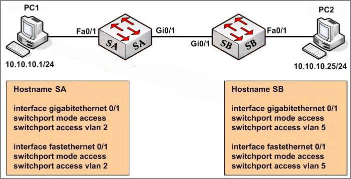
Study the exhibit carefully. Both host stations are part of the same subnet but are in different VLANs. On the basis of the information presented in the exhibit, which statement is true about an attempt to ping from host to host?
 A – Layer 3 device is needed for the ping command to be successful.
B – A trunk port will need to be configured on the link between SA and SB for the ping command to be successful.
C – The two different hosts will need to be in the same VLAN in order for the ping command to be successful.
D – The ping command will be successful without any further configuration changes.
Answer: D
Explanation:
For two hosts in different VLANs, we must use a layer 3 device to transport packages between them. However, in this case both switches are set in “access” mode therefore the VLAN information sent between them will be set as untagged. Moreover, they are in the same subnet so they can ping each other without a layer 3 device.
Question 2:
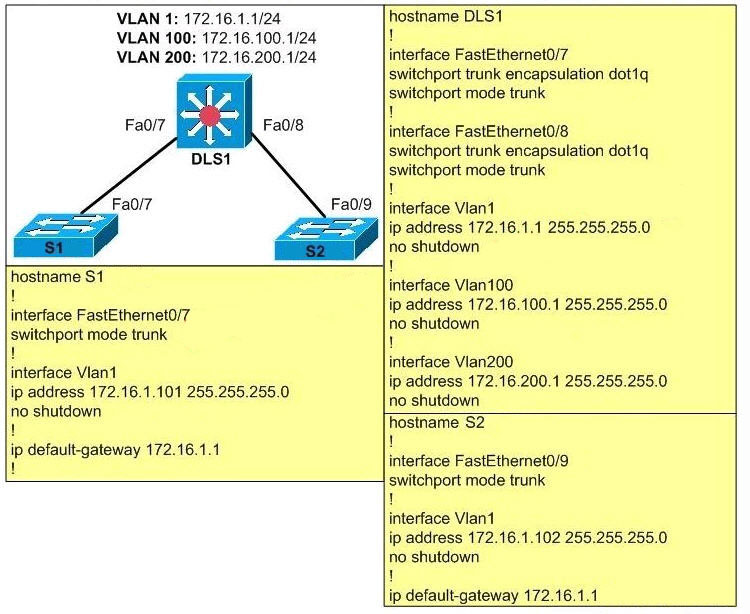
Based on the following exhibit, which problem is preventing users on VLAN 100 from pinging addresses on VLAN 200?
 A – Native VLAN mismatch.
B – Subinterfaces should be created on Fa0/7 and Fa0/8 on DLS1.
C – Trunking needs to be enabled.
D – The ip routing command is missing on DLS1.
Answer: D
Explanation:
To allow communication between two VLANs, we need to enables Layer 3 routing on the switch with the “ip routing” command. Some flatforms are enabled by default but some are not.
Question 3:
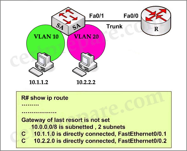
Based on the network diagram and routing table output in the exhibit, which one of these statements is true?
 A – InterVLAN routing has been configured properly, and the workstations have connectivity to each other.
B – InterVLAN routing will not occur since no routing protocol has been configured.
C – Although interVLAN routing is not enabled, both workstations will have connectivity to each other.
D – Although interVLAN routing is enabled, the workstations will not have connectivity to each other.
E – None of the above.
Answer: A
Explanation:
In the output we can see both VLAN10 and VLAN20 are shown up (as networks 10.1.1.0 and 10.2.2.0) so the routing has been configured properly. Notice that the “C” letter indicates that these networks are directly connected with the router.
Question 4:
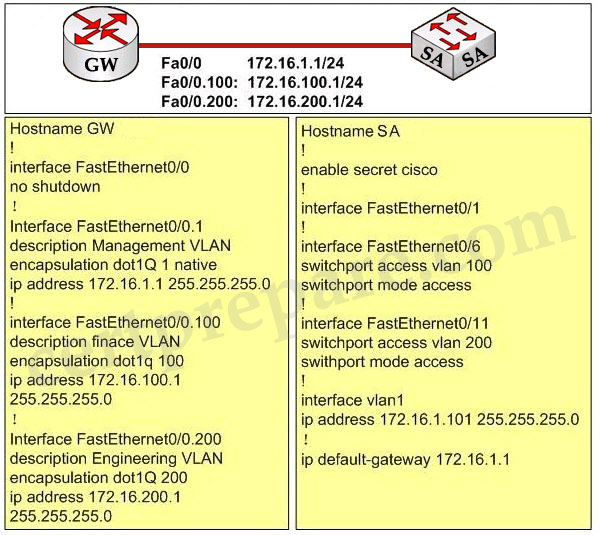
Study the following exhibit carefully, what is the reason that users from VLAN 100 can’t ping users on VLAN 200?
 A – IP routing needs to be enabled on the switch
B – Trunking needs to be enabled on Fa0/1
C – VLAN 1 needs the no shutdown command
D – The native VLAN is wrong
Answer: B
Explanation:
The Fa0/1 interface on the switch is not configured with trunking mode. It needs to be configured as shown below:
SA(config)#interface Fa0/1
SA(config-if)#switchport mode trunk
SA(config-if)#switchport trunk encapsulation dot1q
Question 5:
Assume that a host sends a packet to a destination IP address and that the CEF-based switch does not yet have a valid MAC address for the destination. How is the ARP entry (MAC address) of the next-hop destination in the FIB get?
A – The sending host must send an ARP request for it
B – All packets to the destination are dropped
C – The Layer 3 forwarding engine (CEF hardware) must send an ARP request for it
D – CEF must wait until the Layer 3 engine sends an ARP request for it
Answer: D
Explanation:
If a valid MAC address for the destination is not found, the Layer 3 forwarding engine can’t forward the packet in hardware due to the missing Layer 2 next-hop address. Therefore the packet is sent to the Layer 3 Engine so that it can generate an ARP request (this is called the “CEF glean” state)
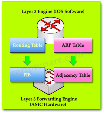
Answer: A D
Question 1:
Study the exhibit carefully. Both host stations are part of the same subnet but are in different VLANs. On the basis of the information presented in the exhibit, which statement is true about an attempt to ping from host to host?

B – A trunk port will need to be configured on the link between SA and SB for the ping command to be successful.
C – The two different hosts will need to be in the same VLAN in order for the ping command to be successful.
D – The ping command will be successful without any further configuration changes.
Answer: D
Explanation:
For two hosts in different VLANs, we must use a layer 3 device to transport packages between them. However, in this case both switches are set in “access” mode therefore the VLAN information sent between them will be set as untagged. Moreover, they are in the same subnet so they can ping each other without a layer 3 device.
Question 2:
Based on the following exhibit, which problem is preventing users on VLAN 100 from pinging addresses on VLAN 200?

B – Subinterfaces should be created on Fa0/7 and Fa0/8 on DLS1.
C – Trunking needs to be enabled.
D – The ip routing command is missing on DLS1.
Answer: D
Explanation:
To allow communication between two VLANs, we need to enables Layer 3 routing on the switch with the “ip routing” command. Some flatforms are enabled by default but some are not.
Question 3:
Based on the network diagram and routing table output in the exhibit, which one of these statements is true?

B – InterVLAN routing will not occur since no routing protocol has been configured.
C – Although interVLAN routing is not enabled, both workstations will have connectivity to each other.
D – Although interVLAN routing is enabled, the workstations will not have connectivity to each other.
E – None of the above.
Answer: A
Explanation:
In the output we can see both VLAN10 and VLAN20 are shown up (as networks 10.1.1.0 and 10.2.2.0) so the routing has been configured properly. Notice that the “C” letter indicates that these networks are directly connected with the router.
Question 4:
Study the following exhibit carefully, what is the reason that users from VLAN 100 can’t ping users on VLAN 200?

B – Trunking needs to be enabled on Fa0/1
C – VLAN 1 needs the no shutdown command
D – The native VLAN is wrong
Answer: B
Explanation:
The Fa0/1 interface on the switch is not configured with trunking mode. It needs to be configured as shown below:
SA(config)#interface Fa0/1
SA(config-if)#switchport mode trunk
SA(config-if)#switchport trunk encapsulation dot1q
Question 5:
Assume that a host sends a packet to a destination IP address and that the CEF-based switch does not yet have a valid MAC address for the destination. How is the ARP entry (MAC address) of the next-hop destination in the FIB get?
A – The sending host must send an ARP request for it
B – All packets to the destination are dropped
C – The Layer 3 forwarding engine (CEF hardware) must send an ARP request for it
D – CEF must wait until the Layer 3 engine sends an ARP request for it
Answer: D
Explanation:
If a valid MAC address for the destination is not found, the Layer 3 forwarding engine can’t forward the packet in hardware due to the missing Layer 2 next-hop address. Therefore the packet is sent to the Layer 3 Engine so that it can generate an ARP request (this is called the “CEF glean” state)

Question 6:
CEF is a complete new routing switch technology . Which two table types are CEF components?(Choose two)
A – adjacency tables
B – caching tables
C – neighbor tables
D – forwarding information base
B – caching tables
C – neighbor tables
D – forwarding information base
Answer: A D